Raymarine Linear Drive Autohelm Installation on Nicknack
When Nicknack was purchased in 2003 it came with an Autohelm 6000 linear drive autohelm. After the initial season I started having continuously intermittent problems seemingly caused by loose connections or cold solder joints. I decided that it was time to replace it with something I could interface into more modern electronics and as an often solo sailor this system was the lifeblood of the boat.
I choose Raymarine because they had a good reputation and also it looked like it would be an easy direct replacement for the existing unit. The one problem I found was the the drive to base design was changed from the 6000 extending the ram length by about 2 inches. The 6000 had fit nicely on a shelf in the T37 (which does not seem to be standard) but the new drive had to be mounted slightly higher where the boat was wider to get the necessary length for the system. This meant building and glassing in a shelf to mount the base to. To do this I took some spare balsa core and built 3 sides of a cube with glass cloth and epoxy after shaping the hull side to match shapes. I then tabbed this shelf into position on the hull and mounted the drive. Make sure you pre-drill the holes.
You'll want to do as much work before you climb below as this will even challenge the contorsionist in the circus. These beautiful classic sailboats were never designed for an autohelm.
Note that after 2 years with setup the base bracket vibrated loose while sailing solo on a 12 reach with the spinnaker up. When I reached in to figure out the problem I noticed two nuts were loose and one nut had fallen off. Since they had been mounted with a washer and lock washer I thought it would be wise to use a Nylock nut. After going to my spare parts container and finding what I thought were the right size nuts, I discovered that the original bolts had metric size threads and I didn't carry any spare metrics. Well, I also don't carry metric size wrenches so now I had to tighten the loose nuts with a crescent wrench. Not fun, and all this while still reaching with the spinnker on a broad reach. I also found the fallen nuts and was able to completely secure the bracket. After arriving back at home I then replaced all the mounting bolts with readily available hardware. I thought we were switching to the metric system!
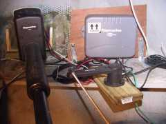
Click on picture for larger view.
|
Overall view of most the of the SG1 parts, Drive - Computer - Rudder Transducer. What you don't see is the Fluxgate compass.
|
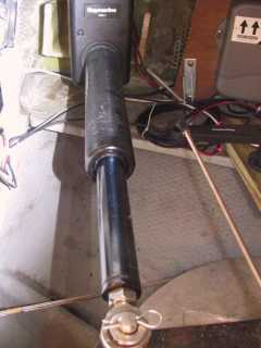
Click on picture for larger view. |
This area is tight to work in and just as tight to take a picture of.
|
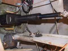
Click on picture for larger view. |
This area is tight to work in and just as tight to take a picture of.
|
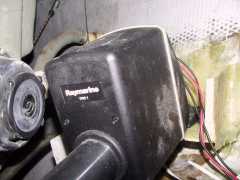
Click on picture for larger view. |
Tighter shot of linear drive mounting shelf.
|
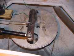
Click on picture for larger view. |
The rudder arm is a collar that fits over the rudder post with a bolt through it and the arm welded on. This system matches the emergency tiller system that probably came with the T37c so to switch to the emergency tiller you would need to remove the arm and bolt and attach the emergency tiller re-inserting the bolt. As this came with the boat, I do not know the origins. Others have talked about mounting the drive to the steering quadrant but I recommend you talk to the manufacturer (Edson) for their recomendations.
|


